Spanning tree protocol

In this experiment, we will see how broadcast storms can occur in a network with bridge loops (multiple Layer 2 paths between endpoints). Then, we will see how the spanning tree protocol creates a loop-free logical topology in a network with physical loops, so that a broadcast storm cannot occur. We will also see how the spanning tree protocol reacts when the topology changes.
It should take about 1 hour to run this experiment. (This does not include the time to answer the questions in the Exercise section, which will take some additional time.)
You can run this experiment on CloudLab. Refer to the testbed-specific prerequisites listed below.
Cloudlab-specific instructions: Prerequisites
To reproduce this experiment on Cloudlab, you will need an account on Cloudlab, you will need to have joined a project, and you will need to have set up SSH access.
FABRIC-specific instructions: Prerequisites
This experiment is not supported on the FABRIC testbed. FABRIC does not support true "broadcast" Ethernet service on SharedNIC interfaces.
Chameleon-specific instructions: Prerequisites
This experiment is not supported on the Chameleon testbed. It requires true "broadcast" Ethernet service, which is not supported on Chameleon.
- Skip to Results
- Skip to Run my experiment
Background
An Ethernet switch or bridge relays Ethernet frames between devices connected to different ports. It thereby links multiple hosts (or smaller network segments each with multiple hosts) into a single connected network.
When a frame arrives at a switch or a bridge, the forwarding table is used to determine whether to forward, filter, or flood the frame, depending on its destination address:
- When the switch receives a frame that is destined for an address that is not in the table, the switch will flood the frame out of all ports other than the port on which it arrived.
- If the destination address is in the table, and is known to be reachable on the same port that the frame was received on, the switch will filter (drop) the frame.
- Otherwise, the switch will forward the frame out of the port corresponding to its destination address in the forwarding table.
While this usually works well, problems arise in the event of a bridging loop. For various reasons (e.g. redundancy in case of a link failure), a network may have multiple Layer 2 paths between two endpoints - a bridging loop. This can lead to a broadcast storm:
- When a broadcast packet arrives at a switch, copies will be flooded out all ports other than the one it arrives on.
- Other switches in the network will also flood copies of the packet out all ports other than the one it arrives on.
- Eventually, it will re-appear at the switch that first flooded the packet - but on a different port than the one it originally arrived on. Copies will be flooded out all other ports, including the port that the packet was first seen on.
- As more and more copies are created, the large volume of copies can saturate the network, preventing other traffic from getting through.
- Because Ethernet frames do not have a time-to-live (TTL) field, like IP packets, they will not be discarded - copies of the frame can keep circulating in the network forever.
The spanning tree protocol addresses this issue in a network with physical loops by setting some redundant paths to a blocked state and leaving others in a forwarding state. This creates a loop-free logical topology, so that a broadcast storm cannot occur. However, the network still benefits from the added reliability of redundant paths: if a link that is in a forwarding state becomes unavailable, then the protocol will reconfigure the tree and re-active blocked paths as necessary, to restore connectivity.

To create a loop-free tree, bridges in the network exchange BPDUs, and execute the spanning tree protocol as follows:
- Elect a root switch or bridge. Each bridge is assigned a unique bridge ID, usually formed from a priority concatenated with the MAC address of one of the bridge ports. The bridge or switch with the lowest bridge ID is elected as the root bridge.
- Elect a root port on each non-root bridge. Each bridge (except the root bridge) computes the root path cost, i.e. cost of the path to the root bridge, through each port. Then, the root port is elected - the one with the lowest root path cost.
- Select a designated bridge and port on each network segment. The bridge on each network segment with the lowest root path cost will be selected as the designated bridge, and the port that connects that bridge to the network segment is the designated port. (The sender's bridge ID, then bridge port, is used as the tie-breaker in case there are multiple bridges on a network segment with the same root path cost. The lowest bridge ID or bridge port "wins".)
- Set bridge ports' states. On a bridge that is not the root, only root ports or designated ports can forward frames on a network segment. Other bridge ports are set to the "blocked" state.
In this experiment, we will create a topology with a loop, then watch as the spanning tree algorithm creates a logical loop-free topology.
Results
(Note: the videos in this article were recorded following instructions using the older ifconfig utility, but the instructions have since been updated to use ip instead.)
When the spanning tree protocol is not enabled, we observe that sending a broadcast frame on the network leads to a broadcast storm:
Once we start the spanning tree protocol, we will see how a logical loop-free topology is created in the network, with at least one bridge port ending up in the "blocked" state. We can also identify the root bridge (with a path cost of 0), and the designated port for each network segment:
We will see that a broadcast storm is not triggered in the spanning tree-enabled network:
Finally, we will observe how the spanning tree protocol adapts to changes in the topology. After bringing down the root bridge, we will see a temporary loss in connectivity between two end hosts, then a change in bridge port state on some bridges and re-establishment of a link (following a different Layer 2 path):
Run my experiment
First, you will reserve a topology that includes four bridges connected in a loop, with one host also connected to each LAN:
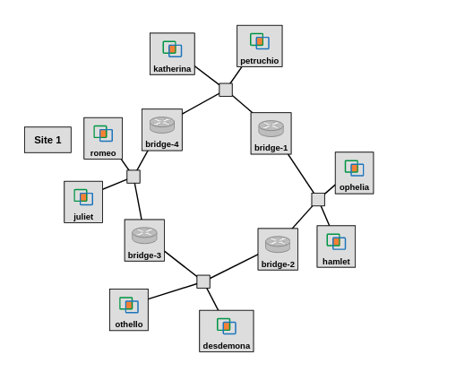
with each interface assigned an IP address as follows:
| Host | on network segment | IP address |
|---|---|---|
| romeo | 3-4 | 10.10.0.100 |
| hamlet | 1-2 | 10.10.0.102 |
| othello | 2-3 | 10.10.0.104 |
| petruchio | 1-4 | 10.10.0.106 |
Setup
Follow the instructions to reserve the resources and log in to each of the hosts and bridges in this experiment.
Cloudlab-specific instructions: Reserve resources
To reserve these resources on Cloudlab, open this profile page:
Click "next", then select the Cloudlab project that you are part of and a Cloudlab cluster with available resources. (This experiment is compatible with any of the Cloudlab clusters.) Then click "next", and "finish".
Wait until all of the resources have turned green and have a small check mark in the top right corner of the "topology view" tab, indicating that they are fully configured and ready to log in. Then, click on "list view" to get SSH login details for the hosts and bridged. Use these details to SSH into each.
When you have logged in to each node, continue to the next section.
Next, we will set up the bridge nodes.
Follow the setup procedure in this section on each bridge node. (It may be quickest to bring up four terminals, each logged in to another bridge node, then copy each command and paste it into all four terminals at once. That way, you will set up all the bridge nodes together.)
Flush the IP address on each experiment interface - since a bridge operates at Layer 2, bridge interfaces do not need an IP address:
sudo ip addr flush dev eth1
sudo ip addr flush dev eth2
Next, run
sudo apt-get update
sudo apt-get -y install bridge-utils nload
to install the bridge utilities, and also the nload utility for monitoring load on the network.
Then, create a new bridge interface named br0 with the command
sudo ip link add br0 type bridgeand add the two experiment interfaces to the bridge:
sudo ip link set eth1 master br0
sudo ip link set eth2 master br0
In the next part of this experiment, we will deliberately trigger a broadcast storm by sending a broadcast frame through this network of bridges. However, there is some background network protocol traffic in the network that may trigger a broadcast storm automatically, even before we send our own broadcast frame! To make it less likely that a broadcast storm will be triggered by automatic network protocol traffic, we will turn off multicast frame flooding on our bridges.
sudo bridge link set dev eth1 mcast_flood off
sudo bridge link set dev eth2 mcast_flood off
echo '0' | sudo tee -a /sys/class/net/br0/bridge/multicast_snooping
Then, we can bring the bridge interface up:
sudo ip link set br0 upAt this point, you should be able to list the bridge ports with
brctl show br0
The output should look something like this:
bridge name	bridge id		STP enabled	interfaces
br0		8000.02b0102cb433	no		eth1
                                       eth2
Note that the spanning tree algorithm is not enabled.
Create a broadcast storm
The spanning tree protocol creates a loop-free forwarding topology, so as to avoid a broadcast storm. In this part of the experiment, we will create a broadcast storm. Here's what this part of the experiment will look like:
To start, open an SSH terminal to each bridge node, and run
sudo tcpdump -i br0 -c 50 "icmp"
in each, to monitor traffic on the bridge interface (both traffic entering and traffic leaving, on all ports). Since we are expecting many frames to be flooded here, we'll stop capturing after 50 packets. (We won't save the packet capture to a file.)
Also, open another SSH terminal to any one bridge node, and on it, run
nload br0
to monitor traffic on the bridge interface.
Finally, open an SSH terminal on the host named "romeo", and run
ping -b -c 1 10.10.0.255
to send one broadcast packet on the LAN. (The -b flag is required when sending a ping to a broadcast address.) Note that this frame will use the broadcast address ff:ff:ff:ff:ff:ff as the destination MAC address.
Observe the nload output. Do you see a sudden increase in network load - much more than you would expect from a single packet?
Check the tcpdump processes running on the four bridge nodes. Can you see the many copies of the same ICMP packet? Look at the ID and sequence fields in the ICMP header, which are used to help match ICMP requests and responses - each ICMP "session" gets a unique ID, and the sequence number is incremented on each subsequent ICMP request in the same session. Are the packets you see in your tcpdump output different ICMP requests, or are they all copies of the same request? How can you tell?
After you have observed the broadcast storm, stop it by running
sudo ip link set br0 downon one bridge node, to break the loop. Wait a few seconds, then bring the bridge back up on the same node with
sudo ip link set br0 upSet up bridges to use spanning tree algorithm
Next, we will set up the bridges to use the spanning tree algorithm. We will see how a logical loop-free topology is created in the network, with at least one bridge port ending up in the "blocked" state. We can also identify the root bridge (with a path cost of 0), and the designated port for each network segment:
On each bridge node, bring down the bridge interface:
sudo ip link set br0 downRun
sudo brctl stp br0 on
to turn on the spanning tree algorithm.
Start tcpdump running on a host on each LAN to capture the BPDUs through which the spanning tree algorithm will be executed. On each of romeo (LAN 3-4), hamlet (LAN 1-2), othello (LAN 2-3), and petruchio (LAN 1-4), run
sudo tcpdump -i eth1 stp -w stp-$(hostname -s).pcap
Then, bring the bridge interface back up with
sudo ip link set br0 upFinally, run
watch --interval 1 brctl showstp br0
on each bridge. This will run the command to show the state of the ports on each bridge (brctl showstp br0) repeatedly, every second, so that you can monitor all the bridge ports as the spanning tree algorithm is executed.
Note: if your screen is not big enough, you may not be able to see all of the output. Since the output is updated continuously every second, you won't be able to scroll. You may want to reduce your zoom or font settings in your terminal, to see the complete output.
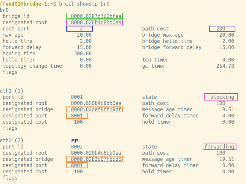
After some time, you should be able to find a bridge that has one port in the "blocking" state, like this:
br0
 bridge id                  8000.02d83a9e5245
 designated root            8000.020327a37077
 root port                  1                       path cost               200
 max age                    20.00                   bridge max age          20.00
 hello time                 2.00                    bridge hello time       2.00
 forward delay              15.00                   bridge forward delay    15.00
 ageing time                300.00
 hello timer                0.00                    tcn timer               0.00
 topology change timer      0.00                    gc timer                226.26
 flags          TOPOLOGY_CHANGE


eth1 (1)
 port id                    8001                    state            forwarding
 designated root            8000.020327a37077       path cost               100
 designated bridge          8000.026f041efece       message age timer     19.28
 designated port            8001                    forward delay timer    0.00
 designated cost            100                     hold timer             0.06
 flags

eth2 (2)
 port id                    8002                    state              blocking
 designated root            8000.020327a37077       path cost               100
 designated bridge          8000.02b0102cb433       message age timer     19.27
 designated port            8001                    forward delay timer    0.00
 designated cost            100                     hold timer             0.05
 flags
You won't be able to copy the terminal contents while the watch process is still running. To save the output, stop the brctl and tcpdump instances with Ctrl+C. Then run
brctl showstp br0
one last time on each bridge, and save the output. Transfer the packet captures to your own laptop with scp. Open the packet capture in Wireshark, and look at a BPDU; make sure you can identify the root ID, root path cost, bridge ID, and port ID in the BPDU.
Then, draw the spanning tree produced in your experiment, and justify your drawing using the BPDUs you collected and output of brctl showstp br0.
Testing the loop-free topology
Let us verify that with the spanning tree algorithm in place to ensure a loop-free topology, a broadcast storm cannot occur. We should see that with the spanning tree protocol creating a logical loop-free topology, we can send a broadcast packet without creating a broadcast storm:
On each bridge node, run
sudo tcpdump -i br0 "icmp"
and then, on "romeo", run
ping -b -c 1 10.10.0.255
to generate a single broadcast packet.
How many times does the ICMP packet appear on each bridge? Does it reach every network segment? Does a broadcast storm occur?
Reacting to changes in the topology
Finally, we will observe how the spanning tree protocol adapts to changes in the topology. After bringing down the root bridge, we will see a temporary loss in connectivity between two end hosts, then a change in bridge port state on some bridges and re-establishment of a link (following a different Layer 2 path):
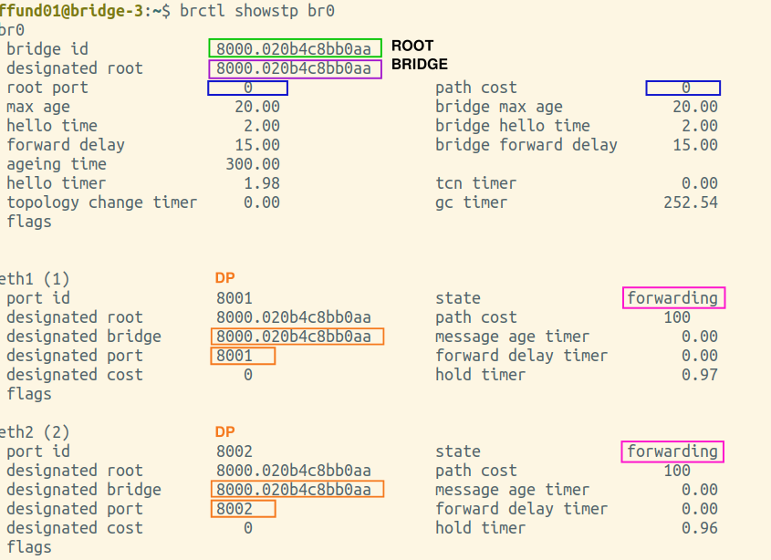
Choose two "host" nodes that are on opposite "sides" of the tree (on opposites sides of the root bridge. The root bridge is easily identified from the brctl showstp br0 output as the one with a path cost of 0).
From one of the two hosts, start to ping the other. For example, if you are using "othello" and "hamlet", on "othello" you might run
ping 10.10.0.102
On the second host - the one that is the target of the pings - use tcpdump to capture ICMP packets:
sudo tcpdump -i eth1 -w icmp-change-$(hostname -s).pcap
On the other three hosts, run
sudo tcpdump -i eth1 -w stp-change-$(hostname -s).pcap
Also, on each bridge, run
watch --interval 1 brctl showstp br0
Then, on the bridge node that is the root bridge in the spanning tree, bring the bridge interface down with
sudo ip link set br0 downWatch the output of the brctl showstp br0 command on the other bridges, and see how they reconfigure themselves to work around the change in the topology. How long does it take before the "ping" messages you are sending start to get a response again?
Once the ping messages are getting through again, stop the tcpdump instances, and use brctl showstp br0 to get the bridge port state on all four bridges and save it to a file. Use scp to transfer these to your laptop.
Then, draw the new spanning tree, and justify it using the BPDUs you have captured and the output of the brctl showstp br0 command.
Notes
This exercise is based on Chapter 3 of TCP/IP Essentials: A Lab-Based Approach.
Exercise
Answer the following questions:
Exercise 1. Broadcast storm
Why does a broadcast storm occur specifically when there is a loop in the network? Even though a small number of broadcast packets are sent, the load in the network is high - why?
Why does this occur specifically with broadcast frame? Why does this not occur when you send a unicast frame to a host that is in the network?
Exercise 2. Set up bridges to use spanning tree algorithm
In this question, you will show how the bridges in the loop form a spanning tree.
You will need screenshots of the final output of brctl showstp br0 from each bridge (after the spanning tree is complete). These screenshots should show the terminal prompt (important - it must show which bridge the output is from!), the command, and the complete output. Open all four screenshots in your preferred image annotation program. You will progressively add annotations as you work on this exercise.
You will also need the BPDUs collected on each network segment (open these in Wireshark).
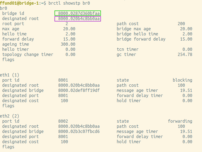
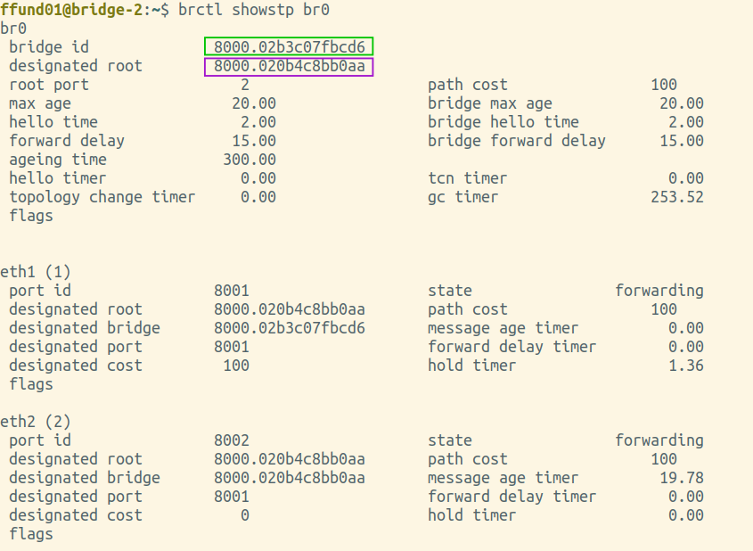
Elect the root bridge
The first step in the spanning tree algorithm is electing a root bridge, the bridge with the lowest bridge ID.
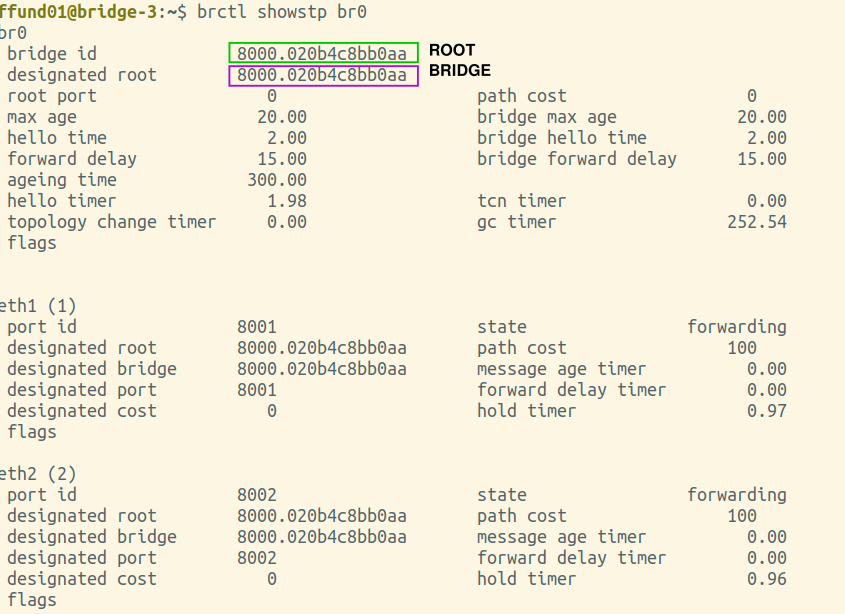
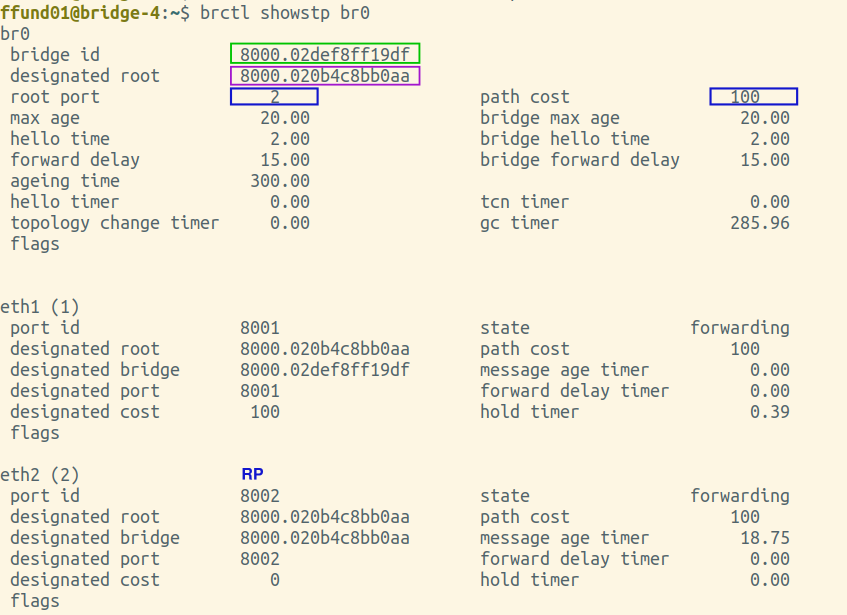
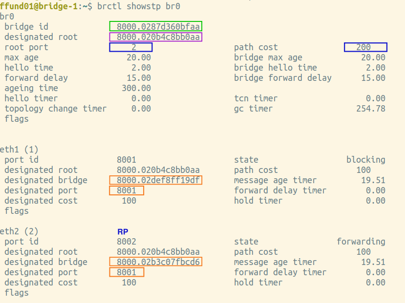
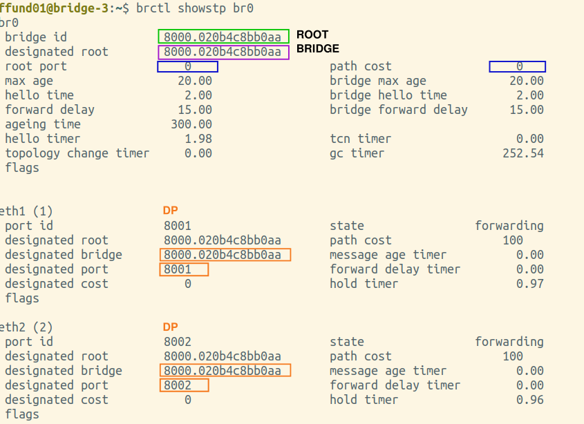
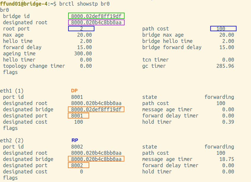
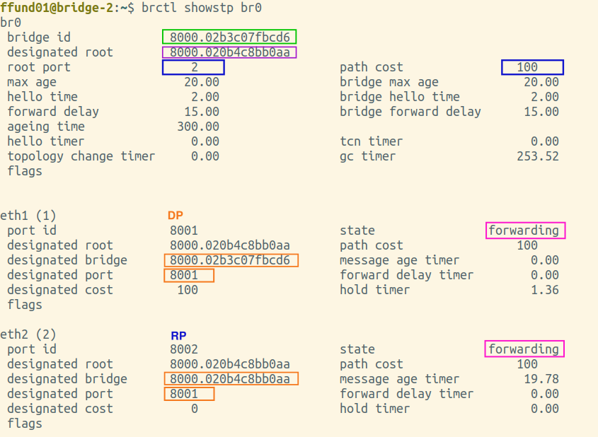
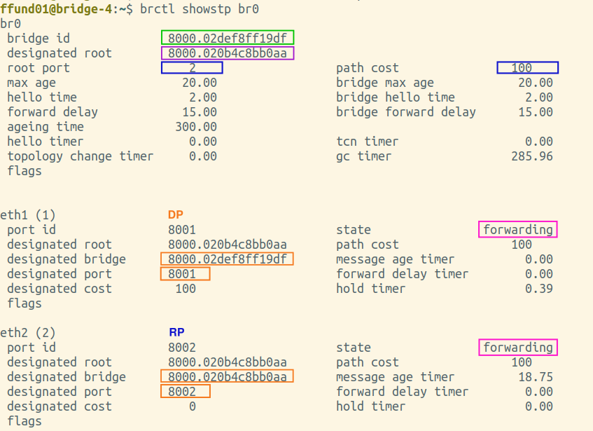
Annotate each of your brctl screenshots by drawing a circle or a box around the bridge ID, and another circle or box around the ID of the "designated root". Also, make a special marking on the screenshot from the root bridge itself (i.e. the one where the bridge ID and designated root are the same).
For example:
 |
 |
 |
 |
Is the root bridge in your experiment bridge-1, bridge-2, bridge-3, or bridge-4?
To elect the root bridge, each bridge initially considers itself the root bridge. Then, bridges exchange spanning tree configuration BPDUs, including a "root identifier" field where they list the ID of the bridge they consider to be the root bridge.
From among the BPDUs you collected, find one where the root bridge in the "root identifier" field is not the same as the final root bridge you identified above. (You're likely to find this near the beginning of a packet capture.)
Note: in Wireshark, the first part of the bridge ID, which is a priority value, is shown in decimal digits in the Packet Details pane, while in the brctl output, it is in hex digits. You can see the ID in hex in Wireshark by highlighting the field in the Packet Details pane and then looking at the Packet Bytes pane.
Take a screenshot showing the Packet Details pane and Packet Bytes pane in Wireshark, with the Root Identifier in this BPDU highlighted. Also note which bridge this BPDU was sent from (use the Bridge ID field in this BPDU to identify the source). Was it sent from bridge-1, bridge-2, bridge-3, or bridge-4?
Upon receiving BPDUs from neighboring bridges, a bridge may see that its neighbor has a different root bridge than itself. If its neighbor's root bridge ID is smaller than the ID of the bridge it currently considers the root, it will update its root bridge to the new, smaller value.
Compare the root bridge ID in the BPDU you showed above, and the ID of the root bridge elected by all the bridges eventually. Give these two values in hex. Which one is greater? Why does the bridge whose BPDU you showed above eventually change its root bridge?
Elect a root port on each non-root bridge
In the second step, each bridge (except the root bridge) computes the root path cost, i.e. cost of the path to the root bridge, through each port. Then, the root port is elected - the one with the lowest root path cost. This is the port that is "facing" the root bridge.
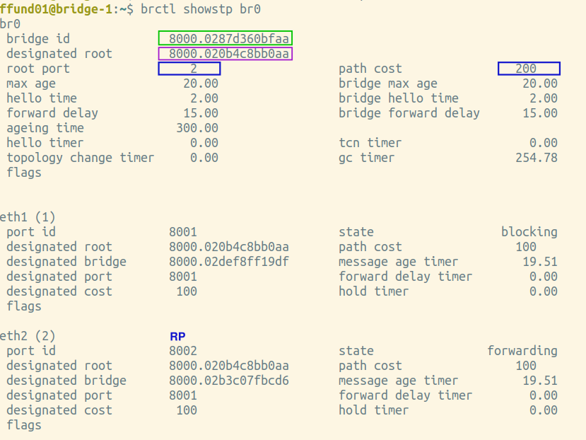
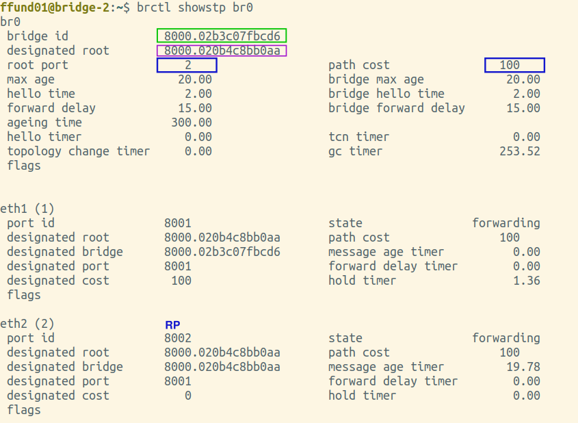
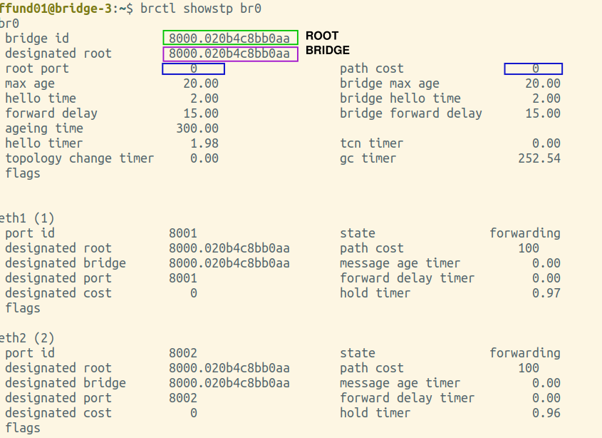
Find the brctl screenshots from your root bridge, and annotate it by drawing a circle or a box around the root port, which is listed near the top of the output. For the root bridge, the root port will be 0 (there is no root port). Also draw a circle or a box around the path cost for the bridge overall, which is shown right next to the root port, near the top of the output.
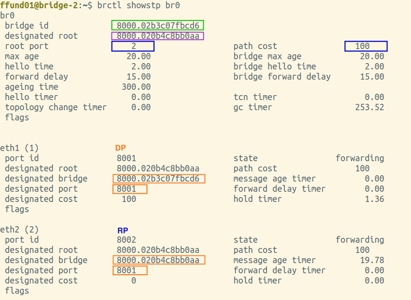
Next, find the brctl screenshots from the two bridges that have one port on the same network segment as the root bridge. This is the port that will be selected as the root port. Annotate these two screenshots by drawing a circle or a box around the root port, which is listed near the top of the output. Also draw a circle or a box around the path cost for the bridge overall, which is shown right next to the root port, near the top of the output. For the port that is the root port, note an "RP" designation in the relevant section in the bottom part of the screenshot.
Then, find the brctl screenshots from the bridge that is farthest from the root bridge. Annotate these two screenshots by drawing a circle or a box around the root port, which is listed near the top of the output. Also draw a circle or a box around the path cost for the bridge overall, which is shown right next to the root port, near the top of the output. For the port that is the root port, note an "RP" designation in the relevant section in the bottom part of the screenshot.
For example:
 |
 |
 |
 |
The bridges find out the path cost (to elect their root ports) by exchanging BPDUs.
From among the BPDUs you collected, find one where the root path cost is zero. Take a screenshot showing the Packet Details pane and Packet Bytes pane in Wireshark, with the Root Path Cost in this BPDU highlighted.
Also make a note of the bridge ID and root ID in this BPDU - is this BPDU sent by the root bridge, or a non-root bridge?
From among the BPDUs you collected, find one where the root path cost is greater than zero. Upload a screenshot showing the Packet Details pane and Packet Bytes pane in Wireshark, with the Root Path Cost in this BPDU highlighted.
Also make a note of the bridge ID and root ID in this BPDU - is this BPDU sent by the root bridge, or a non-root bridge?
Select a designated bridge and port on each network segment
In the third step of the spanning tree protocol, the bridge on each network segment with the lowest root path cost will be selected as the designated bridge, and the port that connects that bridge to the network segment is the designated port.
Find the brctl screenshots from your root bridge, and annotate it by drawing a circle or a box around the designated bridge and designated port (on the designated bridge) for each bridge port. The root bridge will be the designated bridge on any network segment it is connected to.
Next, find the brctl screenshots from the two bridges that have one port on the same network segment as the root bridge. Draw a circle or a box around the designated bridge and designated port for each bridge port, and if this bridge is the designated bridge on the network segment (i.e. the designated bridge is the same as the bridge ID), note a "DP" designation in the relevant section.
For the bridge port on the same network segment as the root bridge, you should see that the root bridge is the designated bridge, since it has the lowest path cost. For the other port, this bridge and port should be the designated bridge and port, since it has a lower path cost than the other bridge connected to this network segment.
Then, find the brctl screenshots from the bridge that is farthest from the root bridge. Draw a circle or a box around the designated bridge and designated port for each bridge port, and if this bridge is the designated bridge on the network segment (i.e. the designated bridge is the same as the bridge ID), note a "DP" designation in the relevant section.
Is this bridge a designated bridge on any network segment (i.e. are any of its ports designated ports)?
Example:
 |
 |
 |
 |
Set bridge ports' states
In the fourth step, on a bridge that is not the root, any bridge port that is neither a root port nor a designated port will be put in the blocked state.
Find the brctl screenshots from the two bridges that have one port on the same network segment on the root bridge. Annotate these by drawing a circle or a box around the status of each port.
Then, find the brctl screenshots from the bridge that is farthest from the root bridge. Annotate it by drawing a circle or a box around the status of each port.
Example:
 |
 |
 |
 |
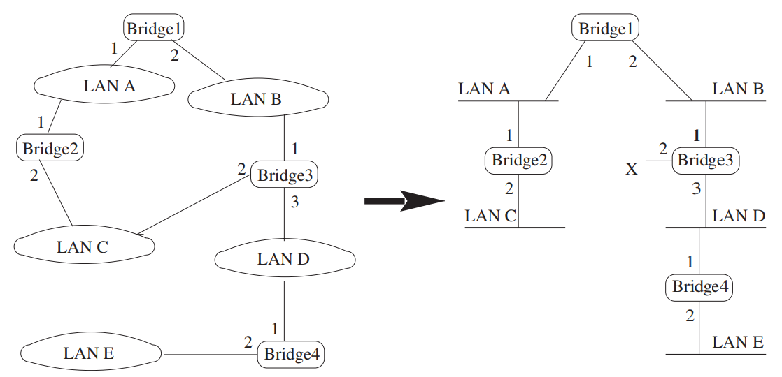
Draw the spanning tree
Finally, draw the spanning tree from this section. You can use this template to create the spanning tree - click the pencil icon and then fill in the values in the shaded boxes. Or, you can draw a spanning tree without the template:
- Put the root bridge at the top of your drawing. Label it "Root bridge". Then, draw each of the other bridges. On each bridge, write its hostname (e.g. "bridge-1", "bridge-2", etc.) Draw links connecting the bridges; label each network segment (e.g. "1-2", "2-3", etc.)
- Label each bridge with its bridge ID, and each port with its port ID (1 or 2).
- If a port is the root port for that bridge, underline its port ID.
- Next to each bridge port, draw a check mark if it is in the forwarding state. If a port is in the blocked state, then draw an X next to it.
- Next to each network segment (1-2, 2-3, 3-4, 1-4), write the designated bridge and the designated port on that bridge (1 or 2) for that network segment.
- Next to each bridge, write the root path cost for that bridge.
Exercise 3. Reacting to changes in the topology
Show the output of the brctl showstp br0 command on each bridge at the end of the section where you practiced "Reacting to changes in the topology". These screenshots should show the terminal prompt (important - it must show which bridge the output is from!), the command, and the complete output.
Also draw the network from the section where you practiced "Reacting to changes in the topology" (i.e. the new spanning tree after you brought down the root bridge), following the same specifications:
- Put the root bridge at the top of your drawing. Draw a circle around the root bridge, and label it "Root". Then, draw each of the other bridges. On each bridge, write its hostname (e.g. "bridge-1", "bridge-2", etc.) Draw links connecting the bridges; label each network segment (e.g. "1-2", "2-3", etc.)
- Label each bridge with its bridge ID, and each port with its port ID (1 or 2).
- If a port is the root port for that bridge, underline its port ID.
- Next to each bridge port, draw a check mark if it is in the forwarding state. If a port is in the blocked state, then draw an X next to it.
- Next to each network segment (1-2, 2-3, 3-4, 1-4), write the designated bridge and the designated port on that bridge (1 or 2) for that network segment.
- Next to each bridge, write the root path cost for that bridge.
Exercise 4. Reaction time to changes
When you changed the topology, how much time elapsed between the last ping request arriving at the target before you brought the root bridge down, and the first ping request arriving at the target after you brought the root bridge down? (Use the packet capture from the network segment on which the target node was located.)
Show evidence from your packet captures to support your answer. For example, show a Wireshark screenshot, and annotate it to circle the latest time that a ping request arrives at the target before you brought the root bridge down, and the earliest time that a ping request arrives at the target after you brought the root bridge down.