Multicast routing with PIM


In this experiment, we will see how multicast routing protocols build a distribution tree between one or more multicast receivers and sources. It should take about 120 minutes to run this experiment.
Cloudlab-specific instructions: Prerequisites
To reproduce this experiment on Cloudlab, you will need an account on Cloudlab, you will need to have joined a project, and you will need to have set up SSH access.
Background
Multicast routing protocols build a loop-free distribution tree of routers that connect the multicast sources and receivers. In this experiment, we will use the Protocol-Independent Multicast (PIM) protocol. (Here, "protocol-independent" means that you can use it together with any unicast routing protocol.)
Since multicast may be used in different use cases, and in different network scenarios, there are several different varieties of PIM. First, there are two modes that differ in how the distribution tree is constructed:
- Dense mode: this mode is designed for a scenario where there are receivers in most parts of the network, and there is plenty of available network capacity. Dense mode builds the multicast tree by flooding multicast traffic throughout the network, then "pruning" back branches where there are no receivers.
- Sparse mode: this mode is designed for the scenario where the multicast receivers are spread out across a wide area of the network, so that many parts of the network have no multicast receivers, and there is not much available network capacity. Sparse mode begins with an empty distribution tree, and adds branches on receiving explicit "join" requests from receivers.
In either case, the distribution tree is dynamic; branches are added and removed as receivers join or leave the multicast group, and send IGMP messages to communicate their intent.
Second, there are two types of trees:
- a shared tree is rooted at a designated point in the network called the Rendezvous Point (RP). The major benefit of a shared tree is that it supports many sources to many receivers multicast, a.k.a. Any Source Multicast (ASM). In a routing table, this will appear as (*,G), where G is the multicast group ID and the asterisk character denotes that receivers will get data from all sources sending to this group.
- a source tree is rooted at the source of the content. This tree only supports one source to many receivers multicast, a.k.a. Source Specific Multicast (SSM). In a routing table, this will appear as (S,G), where S is the unicast IP address of the source and G is the multicast group ID. If there are multiple sources sending to the group, each will have its own distribution tree, and the receivers must join each group.

In this experiment, we will use a shared tree in PIM sparse mode.
Run my experiment
Cloudlab-specific instructions: Reserve resources
To reserve these resources on Cloudlab, open this profile page:
Click "next", then select the Cloudlab project that you are part of and a Cloudlab cluster with available resources. (This experiment is compatible with any of the Cloudlab clusters.) Then click "next", and "finish".
Wait until all of the resources have turned green and have a small check mark in the top right corner of the "topology view" tab, indicating that they are fully configured and ready to log in. Then, click on "list view" to get SSH login details for the hosts and routers. Use these details to SSH into each.
When you have logged in to each node, continue to the next section.
Your multicast routing topology will look like this:

The role of each node in the topology is explained as follows:
- rp will be the rendezvous point, the root of the shared tree in PIM-SM "Any-Source Multicast" mode.
- the routers cr1 and cr2 represent core routers.
- the routers fhr1 and fhr2 are directly connected to the multicast sources source1 and source2, respectively. Routers that are directly connected to a multicast source are known as first hop routers.
- the routers lhr1 and lhr2 are directly connected to the hosts that will be multicast receivers: romeo, juliet, hamlet, and ophelia. Routers that are directly connected to a multicast receiver are known as last hop routers.
When you reserve resources for this experiment, they will be configured as follows:
- Each interface will already be assigned an IP address and subnet mask - use
ip addrto identify the address associated with each network interface. Each host will have static routes for directly connected subnets, but no other routes. - On the routers, the FRR software router will be installed, and will be configured so that the OSPF (unicast routing) and PIM (multicast routing) services are available.
- On the sources and receivers, the VLC media player will be installed. This software can be used to send and receive multimedia streams using multicast.
This software installation can take some time, so you may notice that you have to wait for a few minutes between "resources are up" and "startup tasks have finished, resources are ready to log in".
Configure routing on end hosts
The end hosts in this experiment - both the multicast receivers and sources - will not run any dynamic routing protocol. These should be statically configured to use their local router as a gateway to the rest of the network, for both unicast and multicast traffic.
On source1, run
sudo ip route add 10.10.0.0/16 via 10.10.101.1
sudo ip route add 224.0.0.0/4 dev eth1
On source2, run
sudo ip route add 10.10.0.0/16 via 10.10.102.1
sudo ip route add 224.0.0.0/4 dev eth1
to configure these static routes for the multicast sources.
Next, we'll set up the multicast receivers. On romeo and juliet, run
sudo ip route add 10.10.0.0/16 via 10.10.103.1
sudo ip route add 224.0.0.0/4 dev eth1
On hamlet and ophelia, run
sudo ip route add 10.10.0.0/16 via 10.10.104.1
sudo ip route add 224.0.0.0/4 dev eth1
Configure unicast routing
Now we are ready to set up unicast routing on the routers. You will need to run these steps on every router: rp, cr1, cr2, fhr1, fhr2, lhr1, lhr2.
PIM is protocol-independent, meaning that we could use any underlying unicast routing protocol - static routes, RIP, OSPF, etc. We will use OSPF.
The virtual routers in our experiment run FRR, a software router that includes a shell interface similar to the Cisco IOS interface. Open the router configuration terminal with
VTYSH_PAGER=more
sudo vtysh
At the FRR shell, run
show ip route
and note that the routers initially have routes only for directly connected LANs.
To configure OSPF, enter Global Configuration mode in each router:
configure terminal
The prompt should change (to include a (config) at the end), indicating that you are now in configuration mode.
Then, type
router ospf
to enable OSPF.
Finally, you need to associate one or more networks to the OSPF routing process. Run
network 10.10.0.0/16 area 0.0.0.0
so that all addresses from 10.10.0.0-10.10.255.255 will be enabled for OSPF. (Note: this syntax is slightly different in FRR then in Cisco IOS.)
Then run exit twice, until you are back in the regular FRR shell (not in config mode):
exit
exit
At the FRR shell, run
show ip route
and observe as OSPF routes are added.
Use ping at the end hosts to verify that you can exchange unicast messages across the network. For example, each of romeo, juliet, hamlet, and ophelia should be able to reach both source1 and source2.
Configure multicast routing
Once the unicast routing protocol is set up, we can configure multicast routing.
This section assumes you are still at the FRR shell on each of the routers.
First, we will prepare the rendezvous point. At the FRR shell on the rp router, run:
configure terminal
int eth1
ip pim sm
ip pim rp 10.10.1.100 224.0.0.0/4
ip pim spt-switchover infinity
exit
This will turn on PIM-SM (sparse mode), and set the RP address for all multicast groups as 10.10.1.100. (This is the IP address of the rp node.) Run
show ip pim rp-info
and verify the rendezvous point information.
We also configure the router so that the distribution tree will remain on the shared tree rather than switching to a source tree (this is the spt-switchover setting).
Next, we will configure the two core routers, cr1 and cr2. On these routers, we will turn on PIM-SM and set the RP address for all multicast groups to 10.10.1.100, as with the RP. However, this router has several network interfaces, so we will need to repeat these steps for each interface.
At the FRR shell on cr1 and cr2, run
configure terminal

int eth1
ip pim sm
ip pim rp 10.10.1.100 224.0.0.0/4


int eth2
ip pim sm
ip pim rp 10.10.1.100 224.0.0.0/4


int eth3
ip pim sm
ip pim rp 10.10.1.100 224.0.0.0/4

ip pim spt-switchover infinity

exit
Then, we will configure the routers connected to the multicast sources: fhr1 and fhr2. At the FRR shell on these routers, run:
configure terminal

int eth1
ip pim sm
ip pim rp 10.10.1.100 224.0.0.0/4


int eth2
ip pim sm
ip pim rp 10.10.1.100 224.0.0.0/4

ip pim spt-switchover infinity

exit
Finally, we will configure the routers connected to the multicast receivers.: lhr1 and lhr2, On these routers, we will also need to enable IGMP, since these routers will use the IGMP Join messages from receivers to build the multicast tree. At the FRR shell on these routers, run:
configure terminal

int eth1
ip igmp
ip pim sm
ip pim rp 10.10.1.100 224.0.0.0/4


int eth2
ip igmp
ip pim sm
ip pim rp 10.10.1.100 224.0.0.0/4

ip pim spt-switchover infinity

exit
Prepare to monitor the experiment
For the multicast experiment that follows, you will need a series of terminal windows open to various endpoints. You can prepare these as follows.
In your first terminal window, set up nine terminal panels in three rows, with one in the first row (SSH into the rp), four in the second row (SSH into cr1, cr1, cr2, and cr2) and four in the third row (SSH into fhr1, fhr2, lhr1, lhr2). Then, in each SSH session, run ip addr and make a note of the name of the interface that has the address notes in the following diagram:

You will need to know the interface name corresponding to each "pane" in order to run this experiment. You are strongly encouraged to draw this diagram and note the interface names on the diagram, to help with running the experiment.
Finally, you'll need a terminal window with an SSH session to each multicast receiver, and to source1 and source2.
Build and prune a multicast distribution tree
In this section, we'll see how a multicast distribution tree is constructed, and how parts of the tree are pruned when they are no longer needed.
Start a multicast source
First, in the terminal window that is configured like
you will start a tcpdump on each interface.
In each SSH session on rp, cr1, or cr2, run
sudo tcpdump -nv 'pim and pim[0:1]!=32' -i [INTERFACE]
where in place of [INTERFACE], you substitute the name of the interface indicated in the diagram. This command will capture PIM messages, but will exclude PIM Hello messages (to make it easier to find other relevant messages).
In each SSH session on fhr1, fhr2, lhr1, lhr2, run
sudo tcpdump -nv 'igmp' -i [INTERFACE]
where in place of [INTERFACE], you substitute the name of the interface indicated in the diagram. This command will capture IGMP messages.
On each of the two multicast sources, you will download a video that the source will stream to the receivers. Run
wget https://nyu.box.com/shared/static/6hv8i3is5wahz5b74y934np39rw9v0z0.mp4 -O hdvideo.mp4to download the video.
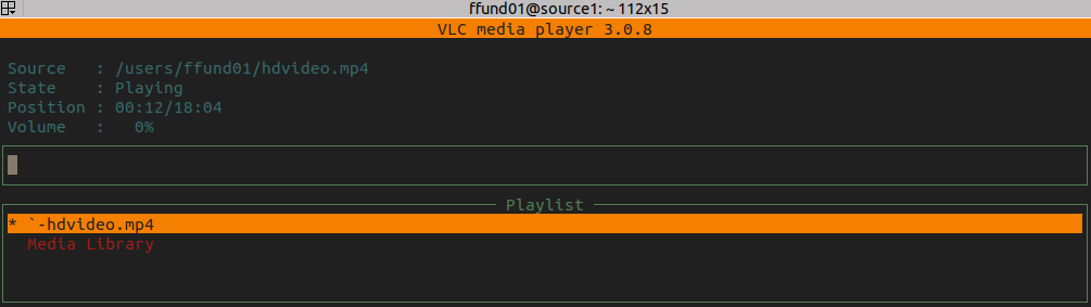
Now we are ready to start a multicast source. On source1, run
vlc --intf ncurses --vout dummy --aout dummy hdvideo.mp4 --sout udp:239.255.12.42 --ttl 6 --repeatto stream the video to the multicast group 239.255.12.42, with TTL 6. In the terminal window, it will show you a display with the video status and a progress bar:
When the first hop router sees a new multicast stream, it will "register" it with the rendezvous point. In the tcpdump windows, look for the PIM Register message from fhr1 to rp:
12:34:10.357677 IP (tos 0xc0, ttl 64, id 563, offset 0, flags [none], proto PIM (103), length 48)
  10.10.101.1 > 10.10.1.100: PIMv2, length 28
  Register, cksum 0x9eff (correct), Flags [ Null ]
  IP (tos 0x0, id 0, offset 0, flags [none], proto PIM (103), length 20, bad cksum 0 (->4f4e)!)
  10.10.101.2 > 239.255.12.42: [|pim]
Note that this message includes information about the multicast source (10.10.101.2) and the group address (239.255.12.42).
The RP will send back a Register Stop message:
12:34:10.359957 IP (tos 0xc0, ttl 63, id 332, offset 0, flags [none], proto PIM (103), length 38)
  10.10.1.100 > 10.10.101.1: PIMv2, length 18
  Register Stop, cksum 0x70a9 (correct) group=239.255.12.42 source=10.10.101.2
Once you have captured these messages, you can stop the tcpdump sessions. In the same arrangement of terminal panes, we will check the network load on each interface. Substituting the correct interface name, run either
nload -a 5 -t 2000 [INTERFACE]
to see a "live" display with a graph, or
nload -a 5 -t 2000 -m [INTERFACE]
if your display is not large enough to see the graphs.
You should see some network traffic on the link between source1 and fhr1. However, fhr1 does not forward this multicast traffic, because there is no receiver interested in it, so you won't see it appear on the other links:
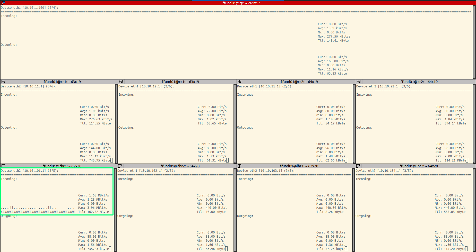
In the nload display, we are especially interested in the value shown next to the word Curr, which shows the current network load on the interface.
(Note that the bit rate of the video traffic will vary according to the content in each frame.)
Once you have noted (and screenshot-ed!) the network load, use Ctrl+C to stop the nload sessions.
Next, on each router, start an FRR router shell with
sudo vtysh
and then run
show ip mroute
For most routers, this multicast routing table will be empty. However, fhr1 is aware of the source:
IP Multicast Routing Table
Flags: S - Sparse, C - Connected, P - Pruned
       R - RP-bit set, F - Register flag, T - SPT-bit set

Source          Group           Flags   Proto  Input            Output           TTL  Uptime
10.10.101.2     239.255.12.42   SFP     none   eth2             none             0    --:--:--
and the RP is also aware of the source:
IP Multicast Routing Table
Flags: S - Sparse, C - Connected, P - Pruned
       R - RP-bit set, F - Register flag, T - SPT-bit set

Source          Group           Flags   Proto  Input            Output           TTL  Uptime
10.10.101.2     239.255.12.42   SP      none   eth1             none             0    --:--:--
Note the "P" flag for this route in both routing tables, which indicates that this multicast flow is "pruned" - it isn't forwarded to receivers.
Use
exit
inside the FRR router shell to return to the regular terminal.
Start a multicast receiver
Again, in the terminal window that is configured like
you will start a tcpdump on each interface.
In each SSH session on rp, cr1, or cr2, run
sudo tcpdump -nv 'pim and pim[0:1]!=32' -i [INTERFACE]
where in place of [INTERFACE], you substitute the name of the interface indicated in the diagram. This command will capture PIM messages, but will exclude PIM Hello messages (to make it easier to find other relevant messages).
In each SSH session on fhr1, fhr2, lhr1, lhr2, run
sudo tcpdump -nv 'igmp' -i [INTERFACE]
where in place of [INTERFACE], you substitute the name of the interface indicated in the diagram. This command will capture IGMP messages.
Next, on romeo, run
vlc --intf ncurses --vout dummy --aout dummy udp://@239.255.12.42 --repeatto receive the multicast stream.
Look at the tcpdump windows. The receiver, romeo, will send an IGMP message to indicate that it is joining the multicast group 239.255.12.42:
11:57:09.768494 IP (tos 0xc0, ttl 1, id 0, offset 0, flags [DF], proto IGMP (2), length 40, options (RA))
  10.10.103.2 > 224.0.0.22: igmp v3 report, 1 group record(s) [gaddr 239.255.12.42 to_ex, 0 source(s)]
The IGMP messages are sent to the multicast group 224.0.0.22.
The last hop router connected to romeo, lhr1, will receive the IGMP message (which is sent to the multicast address 224.0.0.22). This router needs to join the distribution tree for the multicast group indicated in the IGMP message, so it will send a PIM Join message toward its upstream neighbor (the neighbor that is the "next hop" towards the RP):
11:57:09.769774 IP (tos 0xc0, ttl 1, id 72, offset 0, flags [none], proto PIM (103), length 54)
  10.10.21.2 > 224.0.0.13: PIMv2, length 34
  Join / Prune, cksum 0xab48 (correct), upstream-neighbor: 10.10.21.1
    1 group(s), holdtime: 3m30s
      group #1: 239.255.12.42, joined sources: 1, pruned sources: 0
        joined source #1: 10.10.1.100(SWR)
PIM messages are sent to the multicast group 224.0.0.13.
Next, cr2 will receive that PIM Join, and will in turn send a PIM Join message to its upstream neighbor, which is the RP:
11:57:09.771092 IP (tos 0xc0, ttl 1, id 111, offset 0, flags [none], proto PIM (103), length 54)
  10.10.1.2 > 224.0.0.13: PIMv2, length 34
  Join / Prune, cksum 0xbee5 (correct), upstream-neighbor: 10.10.1.100
    1 group(s), holdtime: 3m30s
      group #1: 239.255.12.42, joined sources: 1, pruned sources: 0
        joined source #1: 10.10.1.100(SWR)
The RP knows that 10.10.101.2 is a source for this multicast group, because it appears in its multicast routing table. The RP will send a PIM Join toward the source - its upstream neighbor toward the source is cr1:
11:57:09.771765 IP (tos 0xc0, ttl 1, id 71, offset 0, flags [none], proto PIM (103), length 54)
  10.10.1.100 > 224.0.0.13: PIMv2, length 34
    Join / Prune, cksum 0x5eaa (correct), upstream-neighbor: 10.10.1.1
      1 group(s), holdtime: 3m30s
        group #1: 239.255.12.42, joined sources: 1, pruned sources: 0
          joined source #1: 10.10.101.2(S)
Finally, cr1 will send a PIM Join toward its upstream neighbor for the source, fhr1:
11:57:09.773592 IP (tos 0xc0, ttl 1, id 111, offset 0, flags [none], proto PIM (103), length 54)
  10.10.11.1 > 224.0.0.13: PIMv2, length 34
    Join / Prune, cksum 0x54a9 (correct), upstream-neighbor: 10.10.11.2
      1 group(s), holdtime: 3m30s
        group #1: 239.255.12.42, joined sources: 1, pruned sources: 0
          joined source #1: 10.10.101.2(S)
Once you have captured these messages, you can stop the tcpdump sessions. In the same arrangement of terminal panes, we will check the network load on each interface. Substituting the correct interface name, run either
nload -a 5 -t 2000 [INTERFACE]
to see a "live" display with a graph, or
nload -a 5 -t 2000 -m [INTERFACE]
if your display is not large enough to see the graphs.
Now, there is a distribution tree that includes source1 and romeo, and the multicast traffic appears on each branch in that tree:
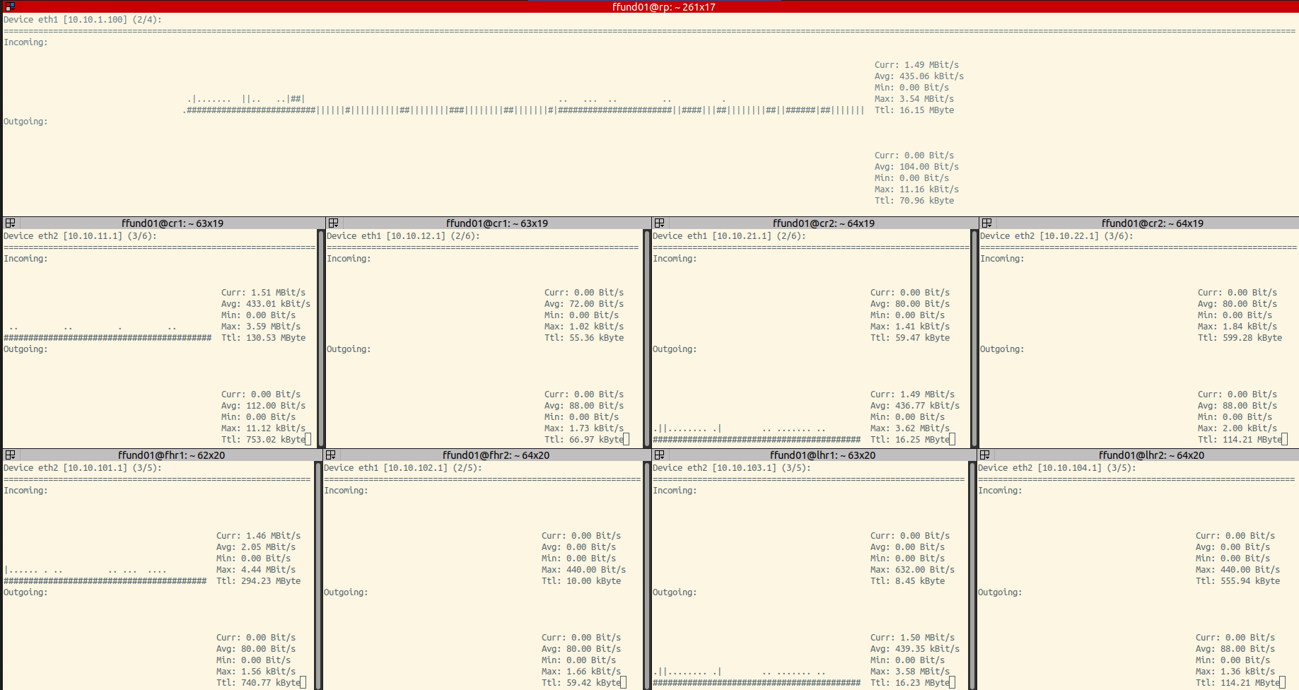
Notice that the branch including source2 is not included, and the branch including the receivers hamlet and ophelia is also not included, since none of those are participating in this multicast group.
Once you have noted (and screenshot-ed!) the network load, use Ctrl+C to stop the nload sessions.
Next, on each router, start an FRR router shell with
sudo vtysh
and then run
show ip mroute
On any router that is a part of the distribution tree between the source and the RP, you'll see an entry similar to this:
Source        Group           Flags   Proto  Input  Output  TTL  Uptime
10.10.101.2   239.255.12.42   ST      PIM    eth2   eth1    1    00:45:59
since these routers belong to distribution tree branches between the source and RP.
On any router that is a part of the distribution tree between the receiver and the RP, you'll see an entry similar to this:
Source        Group           Flags   Proto  Input  Output  TTL  Uptime
*             239.255.12.42   S       PIM    eth2   eth1    1    00:45:59
since these routers belong to the distribution tree for group 239.255.12.42 from any source, not only from 10.10.101.2.
Use
exitinside the FRR router shell to return to the regular terminal.
Start another receiver
Next, add a second multicast receiver: on juliet, run
vlc --intf ncurses --vout dummy --aout dummy udp://@239.255.12.42 --repeatSince juliet is on a network segment that is already part of the multicast distribution tree, the distribution tree will not change.
To validate this, check the network load on each interface following the diagram. Substituting the correct interface name, run either
nload -a 5 -t 2000 [INTERFACE]to see a "live" display with a graph, or
nload -a 5 -t 2000 -m [INTERFACE]if your display is not large enough to see the graphs.
Once you have noted (and screenshot-ed!) the network load, use Ctrl+C to stop the nload sessions.
Leaving a multicast group
Again, in the terminal window that is configured like
you will start a tcpdump on each interface.
In each SSH session on rp, cr1, or cr2, run
sudo tcpdump -nv 'pim and pim[0:1]!=32' -i [INTERFACE]where in place of [INTERFACE], you substitute the name of the interface indicated in the diagram. This command will capture PIM messages, but will exclude PIM Hello messages (to make it easier to find other relevant messages).
In each SSH session on fhr1, fhr2, lhr1, lhr2, run
sudo tcpdump -nv 'igmp' -i [INTERFACE]where in place of [INTERFACE], you substitute the name of the interface indicated in the diagram. This command will capture IGMP messages.
Press Ctrl+C on juliet to stop the video receiver. To leave the group, juliet will send an IGMP membership report with an empty INCLUDE list, which you can observe in the tcpdump window on lhr1:
12:15:58.273875 IP (tos 0xc0, ttl 1, id 0, offset 0, flags [DF], proto IGMP (2), length 40, options (RA))
    10.10.103.3 > 224.0.0.22: igmp v3 report, 1 group record(s) [gaddr 239.255.12.42 to_in, 0 source(s)]
On receiving this IGMP membership report, lhr1 will send an IGMP membership query to the multicast group that juliet just left:
12:15:58.274260 IP (tos 0xc0, ttl 1, id 12539, offset 0, flags [DF], proto IGMP (2), length 40, options (RA))
  10.10.103.1 > 239.255.12.42: igmp query v3 [max resp time 1.0s] [gaddr 239.255.12.42, 1 source(s)]
Since romeo is still interested in receiving this multicast stream, it will send an IGMP membership report indicating as much:
12:15:58.344256 IP (tos 0xc0, ttl 1, id 0, offset 0, flags [DF], proto IGMP (2), length 40, options (RA))
  10.10.103.2 > 224.0.0.22: igmp v3 report, 1 group record(s) [gaddr 239.255.12.42 is_ex, 0 source(s)]
and thus lhr1 knows that it should not prune itself from the multicast distribution tree.
If romeo also leaves, the situation is somewhat different. On romeo, press Ctrl+C to stop the multicast receiver. Again, the receiver sends an IGMP membership report with an empty INCLUDE list, which you'll observe in the tcpdump on lhr1:
12:19:40.376137 IP (tos 0xc0, ttl 1, id 0, offset 0, flags [DF], proto IGMP (2), length 40, options (RA))
  10.10.103.2 > 224.0.0.22: igmp v3 report, 1 group record(s) [gaddr 239.255.12.42 to_in, 0 source(s)]
and again, lhr1 will send an IGMP membership query to find out if there are still interested receivers:
12:19:40.376527 IP (tos 0xc0, ttl 1, id 29196, offset 0, flags [DF], proto IGMP (2), length 40, options (RA))
  10.10.103.1 > 239.255.12.42: igmp query v3 [max resp time 1.0s] [gaddr 239.255.12.42, 1 source(s)]
Since no host responds within the designated time to indicate interest in the multicast group, lhr1 will now send a PIM Prune message toward the RP. You'll see this in the tcpdump window on cr2:
12:19:42.378004 IP (tos 0xc0, ttl 1, id 185, offset 0, flags [none], proto PIM (103), length 54)
  10.10.21.2 > 224.0.0.13: PIMv2, length 34
  Join / Prune, cksum 0xab48 (correct), upstream-neighbor: 10.10.21.1
    1 group(s), holdtime: 3m30s
      group #1: 239.255.12.42, joined sources: 0, pruned sources: 1
        pruned source #1: 10.10.1.100(SWR)
On receiving this message, cr2 will send a PIM Prune towards the RP, which you can observe in the tcpdump window on rp:
12:19:42.378650 IP (tos 0xc0, ttl 1, id 270, offset 0, flags [none], proto PIM (103), length 54)
  10.10.1.2 > 224.0.0.13: PIMv2, length 34
  Join / Prune, cksum 0xbee5 (correct), upstream-neighbor: 10.10.1.100
    1 group(s), holdtime: 3m30s
      group #1: 239.255.12.42, joined sources: 0, pruned sources: 1
        pruned source #1: 10.10.1.100(SWR)
The rendezvous point will prune the "any source" route toward the receiver.
12:19:45.380163 IP (tos 0xc0, ttl 1, id 166, offset 0, flags [none], proto PIM (103), length 54)
  10.10.1.100 > 224.0.0.13: PIMv2, length 34
  Join / Prune, cksum 0xbee5 (correct), upstream-neighbor: 10.10.1.100
    1 group(s), holdtime: 3m30s
      group #1: 239.255.12.42, joined sources: 0, pruned sources: 1
        pruned source #1: 10.10.1.100(SWR)
Since there is no multicast receiver still interested in this group, it will also send a PIM Prune toward the source:
12:19:45.380288 IP (tos 0xc0, ttl 1, id 167, offset 0, flags [none], proto PIM (103), length 54)
  10.10.1.100 > 224.0.0.13: PIMv2, length 34
  Join / Prune, cksum 0x5eaa (correct), upstream-neighbor: 10.10.1.1
    1 group(s), holdtime: 3m30s
      group #1: 239.255.12.42, joined sources: 0, pruned sources: 1
        pruned source #1: 10.10.101.2(S)
And finally, cr1 will send a PIM Prune toward fhr1:
12:19:48.382733 IP (tos 0xc0, ttl 1, id 270, offset 0, flags [none], proto PIM (103), length 54)
  10.10.11.1 > 224.0.0.13: PIMv2, length 34
  Join / Prune, cksum 0x54a9 (correct), upstream-neighbor: 10.10.11.2
    1 group(s), holdtime: 3m30s
      group #1: 239.255.12.42, joined sources: 0, pruned sources: 1
        pruned source #1: 10.10.101.2(S)
Now, the situation is restored to exactly what it was when only the multicast source had started. The multicast traffic is not forwarded by fhr1, and only fhr1 and rp have routes for this multicast group (and these routes have the P flag set, indicating that they are pruned.)
Compare multicast and unicast distribution
Now that we understand how the multicast distribution tree is built and pruned, we'll compare multicast and unicast distribution with respect to the load they induce on the network.
For this experiment, in the terminal window that is configured like
run either
nload -a 5 -t 2000 [INTERFACE]to see a "live" display with a graph, or
nload -a 5 -t 2000 -m [INTERFACE]if your display is not large enough to see the graphs.
We'll start with the multicast case. First, start a multicast source on source1 (if it is not already running):
vlc --intf ncurses --vout dummy --aout dummy hdvideo.mp4 --sout udp:239.255.12.42 --ttl 6 --repeat
Wait about a minute, then take a screenshot of the nload terminal panels, showing the network load on each segment. (Make sure that the Curr part of the nload display, which shows the current network load, is visible for each interface. If you have the nload sessions split across multiple windows, you'll take a screenshot of each.)
Then, start a multicast receiver on romeo:
vlc --intf ncurses --vout dummy --aout dummy udp://@239.255.12.42 --repeatWait about a minute, then take a screenshot of the nload terminal panels, showing the network load on each segment. (Make sure that the Curr part of the nload display, which shows the current network load, is visible for each interface. If you have the nload sessions split across multiple windows, you'll take a screenshot of each.)
Start a multicast receiver on juliet:
vlc --intf ncurses --vout dummy --aout dummy udp://@239.255.12.42 --repeatWait about a minute, then take a screenshot of the nload terminal panels, showing the network load on each segment. (Make sure that the Curr part of the nload display, which shows the current network load, is visible for each interface. If you have the nload sessions split across multiple windows, you'll take a screenshot of each.)
Start a multicast receiver on hamlet:
vlc --intf ncurses --vout dummy --aout dummy udp://@239.255.12.42 --repeatWait about a minute, then take a screenshot of the nload terminal panels, showing the network load on each segment. (Make sure that the Curr part of the nload display, which shows the current network load, is visible for each interface. If you have the nload sessions split across multiple windows, you'll take a screenshot of each.)
Start a multicast receiver on ophelia:
vlc --intf ncurses --vout dummy --aout dummy udp://@239.255.12.42 --repeatWait about a minute, then take a final screenshot of the nload terminal panels, showing the network load on each segment. (Make sure that the Curr part of the nload display, which shows the current network load, is visible for each interface. If you have the nload sessions split across multiple windows, you'll take a screenshot of each.)
Then, use Ctrl+C to stop the multicast source and receivers. There should be no meaningful load on the network at this point.
For the unicast case, we'll look at two different distribution options: UDP and RTP with RTSP.
To stream the video via unicast with UDP, we'll run the following command on source1:
vlc --intf ncurses --vout dummy --aout dummy hdvideo.mp4 --sout '#duplicate{dst=udp{dst=10.10.103.2},dst=udp{dst=10.10.103.3},dst=udp{dst=10.10.104.2},dst=udp{dst=10.10.104.3}}' --repeatThis command specifies that the video should be streamed to each of the four unicast receiver addresses. The source must know the address of each receiver.
Wait about a minute, then take a screenshot of the nload terminal panels, showing the network load on each segment. (Make sure that the Curr part of the nload display, which shows the current network load, is visible for each interface. If you have the nload sessions split across multiple windows, you'll take a screenshot of each.)
You can run a UDP receiver on any of the receiver nodes -
vlc --intf ncurses --vout dummy --aout dummy udp:// --repeathowever, this won't change the network load. The video is streamed to all destination addresses, whether they are actively receiving it or not.
Use Ctrl+C to stop VLC on the source and any receiver nodes where it is running. Make sure the network load goes down to approximately zero.
Then, we'll try RTP with RTSP (unicast, again). With this distribution model, an RTSP session is used to establish a connection between a receiver and source; then, RTP is used to deliver the video content from source to receiver.
On source1, run
vlc --intf ncurses --vout dummy --aout dummy hdvideo.mp4 --sout '#rtp{sdp=rtsp://source1:8080/video.sdp}' --repeatWait about a minute, then take a screenshot of the nload terminal panels, showing the network load on each segment. (Make sure that the Curr part of the nload display, which shows the current network load, is visible for each interface. If you have the nload sessions split across multiple windows, you'll take a screenshot of each.)
Then, start a receiver on romeo:
vlc --intf ncurses --vout dummy --aout dummy rtsp://source1:8080/video.sdp --repeatWait about a minute, then take a screenshot of the nload terminal panels, showing the network load on each segment. (Make sure that the Curr part of the nload display, which shows the current network load, is visible for each interface. If you have the nload sessions split across multiple windows, you'll take a screenshot of each.)
Start a receiver on juliet:
vlc --intf ncurses --vout dummy --aout dummy rtsp://source1:8080/video.sdp --repeatWait about a minute, then take a screenshot of the nload terminal panels, showing the network load on each segment. (Make sure that the Curr part of the nload display, which shows the current network load, is visible for each interface. If you have the nload sessions split across multiple windows, you'll take a screenshot of each.)
Start a receiver on hamlet:
vlc --intf ncurses --vout dummy --aout dummy rtsp://source1:8080/video.sdp --repeatWait about a minute, then take a screenshot of the nload terminal panels, showing the network load on each segment. (Make sure that the Curr part of the nload display, which shows the current network load, is visible for each interface. If you have the nload sessions split across multiple windows, you'll take a screenshot of each.)
Start a receiver on ophelia:
vlc --intf ncurses --vout dummy --aout dummy rtsp://source1:8080/video.sdp --repeatWait about a minute, then take a final screenshot of the nload terminal panels, showing the network load on each segment. (Make sure that the Curr part of the nload display, which shows the current network load, is visible for each interface. If you have the nload sessions split across multiple windows, you'll take a screenshot of each.)
Then, use Ctrl+C to stop the multicast source and receivers. There should be no meaningful load on the network at this point.
In your own words, compare UDP multicast, UDP unicast, and RTP/RTSP unicast for multimedia distribution, with reference to the specific numeric experiment results. Which uses the network most effectively? What are the disadvantages of each approach?
Multicast source
With any-source multicast, a receiver can get content for a multicast group without specifying what source the content should come from.
Suppose that source1 and source2 are sources in an IP television distribution network. Let us further suppose that romeo wants to receive any content that is distributed over this network, while hamlet is only interested in content from source1 (e.g. a specific television program).
For this experiment, in the terminal window that is configured like
run either
nload -a 5 -t 2000 [INTERFACE]to see a "live" display with a graph, or
nload -a 5 -t 2000 -m [INTERFACE]if your display is not large enough to see the graphs.
On source1, start streaming the video to the multicast receivers:
vlc --intf ncurses --vout dummy --aout dummy hdvideo.mp4 --sout udp:239.255.12.42 --ttl 6 --repeatOn romeo, start a multicast receiver for any source:
vlc --intf ncurses --vout dummy --aout dummy udp://@239.255.12.42 --repeatOn hamlet, start a multicast receiver for content from source1 only:
vlc --intf ncurses --vout dummy --aout dummy udp://10.10.101.2@239.255.12.42 --repeat
Look at the network load with nload - you should see that the content is streamed to both romeo's branch of the network and hamlet's branch of the network.
Next, use Ctrl+C to stop the video stream on source1. Start a video stream on source2 to the same multicast group:
vlc --intf ncurses --vout dummy --aout dummy hdvideo.mp4 --sout udp:239.255.12.42 --ttl 6 --repeatLook at the network load on lhr2. You should see that the video is no longer distributed to hamlet, since hamlet was only interested in content from source1.
Notes
Exercise
- Building and pruning a multicast distribution tree:
- From your
tcpdumpoutput, show the PIM message that is sent by each router in turn when the first multicast receiver, romeo, joins the multicast group (with source1 already registered). Annotate each message to show the source and destination address of each message, the address of the upstream neighbor indicated in the message, and the group and source indicated in the message. Also label each screenshot, to indicate the name of the router that sent this message, and to identify the network segment on which the message is sent. - With reference to the packets you captured, explain how the multicast distribution tree is constructed when a receiver joins. Use your own words. Cite any source you use as a reference (even if you paraphrase, you still need to cite the source!)
- From your
tcpdumpoutput, show the PIM message that is sent by each router in turn when the last multicast receiver, romeo, leaves the multicast group. Annotate each message to show the source and destination address of each message, the address of the upstream neighbor indicated in the message, and the group and source indicated in the message. Also label each screenshot, to indicate the name of the router that sent this message, and to identify the network segment on which the message is sent.
- From your
- With reference to the packets you captured, explain how the multicast distribution tree is pruned when the receiver leaves. Use your own words. Cite any source you use as a reference (even if you paraphrase, you still need to cite the source!)
- Compare multicast and unicast distribution:
- Show your screenshots of the network load in each case. In your own words, compare UDP multicast, UDP unicast, and RTP/RTSP unicast for multimedia distribution, with reference to the experiment results. Which uses the network most effectively? What are the disadvantages of each approach?