Channel planning in 802.11: understanding the effect of nearby networks


When neighboring 802.11 networks operate on the same channel, they compete with one another to use the shared medium. In this experiment, you will observe the effect on throughput when neighboring cells operate on the same channel vs. on non-interfering channels.
It should take about 2 hours to run this experiment, but you will need to have reserved that time in advance. This experiment uses wireless resources, and you can only use wireless resources on ORBIT/COSMOS during a reservation.
To reproduce this experiment on ORBIT/COSMOS, you will need an account, and you will need to have joined a project. You should have already uploaded your SSH keys to your profile. Finally, you must have reserved time on the "outdoor" testbed at ORBIT, and you must run this experiment during your reserved time. (Alternatively, you can use "sb4" testbed at ORBIT, with some modifications to the instructions.)
- Skip to Results
- Skip to Run my experiment
Background
There are 14 designated 802.11 channels in the 2.4 GHz range, spaced 5 MHz apart (with the exception of channel 14, which has extra spacing before it). The availability of these channels depends on regulatory domain in which they are operating; in the United States, channels 1-11 are available for use.

Figure 1: 802.11bg channels for the 2.4 GHz band. Channels 1-11 are available in the United States; the largest set of non-overlapping channels is 1, 6, and 11. Image CC BY-SA 3.0, via Wikimedia Commons
.svg)
When two or more access points or wireless clients (stations) that are in range of one another, operate on the same channel, they form one collision domain. If any two devices in the same collision domain transmit at the same time, their radio signals will collide, resulting in corruption or frame loss. Thus, transmission time on the wireless resource is shared among all devices in the collision domain (using CSMA/CA to avoid collisions with any device within range that is on the same channel).
Sometimes, wireless networks that are in range of one another operate on different, but overlapping, channels. This, too, affects the throughput of the networks. In this scenario, traffic from the neighboring network may not be detected by CSMA/CA, but can still cause interference, leading to corruption or frame loss.
When deploying an 802.11 network, it is important to be aware of nearby networks and plan what channels to use with them in mind. In congested areas, it is unlikely that you will find a channel that is unoccupied. However, even then, you can try to avoid the channels that are occupied by networks that are
- very close, so that their signal strength in the area where you want to operate is high, and/or
- very busy, with a lot of traffic.
Various applications are available to help with 802.11 channel planning. The following screenshot shows the wireless access points seen by an Android app in the 2.4 GHz band at the 2 Metrotech Center building at NYU Tandon:
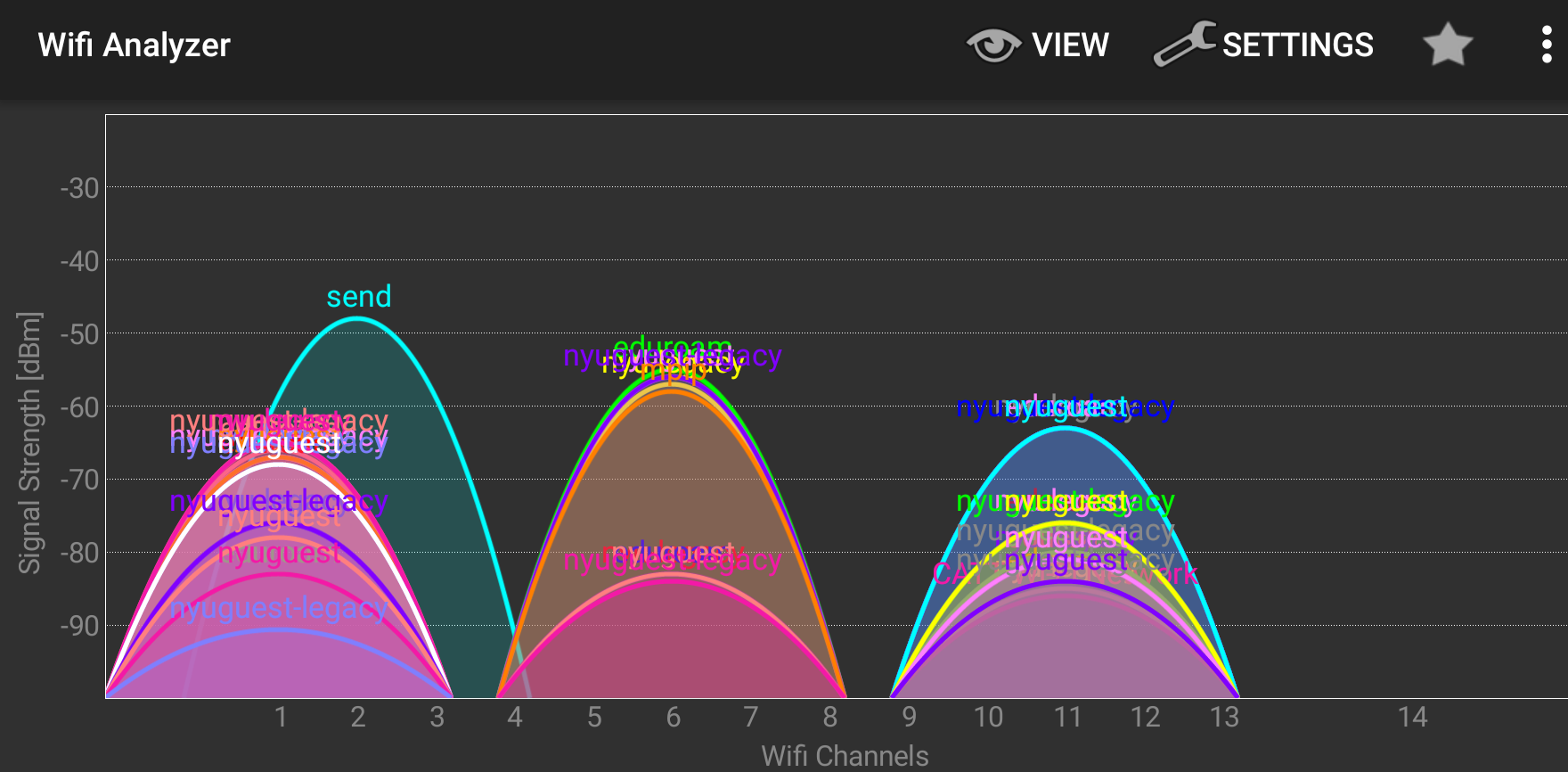
Figure 2: Observed APs in the 2.4 GHz range at NYU, using an Android app.
Results
We find that operating on the same channel effectively halves the throughput of each network, compared to operation on non-overlapping channels (with centers 25 MHz apart, shown on the right in the image below):

Figure 3: The throughput of the "wireless1" network (blue) increases from about 1.85 Mbps to 3.75 Mbps when a nearby network, "wireless2", moves from the same channel to a non-overlapping channel. The throughput of the "wireless2" network (orange) also increases, from 5.32 Mbps to 10.66 Mbps.
Run my experiment
In this experiment, I used the outdoor testbed on ORBIT. To reserve time on this testbed, log in to http://orbit-lab.org, click on "Control Panel", click on "Scheduler", click on the grid squares corresponding to the "outdoor" testbed and the date/time you want, and submit your reservation request. You may then complete the experiment at the reserved time.
(You may alternatively use the sb4 testbed at ORBIT, with some modifications to the instructions.)
On the outdoor testbed at ORBIT, I used six nodes as follows:

They are configured in two groups of three, with each group (denoted by color) belonging to its own wireless network. In each group, one nodes acts as an access point, one node acts as a server that receives traffic, and one node acts as a client that sends traffic.
I use node1-3, node1-4, etc. on the outdoor testbed, as denoted above. However, any six nodes with WiFi capability that are close to one another will work. On the outdoor testbed, it is common for some nodes to be unavailable. You can verify the availability of outdoor nodes and their capabilities as follows:
- Visit http://orbit-lab.org and log in
- Click on "Control Panel"
- Click on "Status Page"
- Choose the "outdoor" tab
- Scroll down to the "WiFi" panel, and check the box next to "Ath9k". (This will mark with an X any node that has a WiFi interface in the Atheros 9xxx family.)
In the display, nodes that are available are shown as blue or green squares; nodes that are not available are shown as red squares. You can find out the name of a node by clicking on it, and then looking at the "Info" panel on the left. Use this information to make substitutions in the instructions, replacing unavailable nodes (if any; shown as red squares) with nearby available nodes that have Atheros 9xxx cards.
Prepare the testbed - outdoor testbed on ORBIT
Follow these instructions if you are using the outdoor testbed at ORBIT.
At your reserved time, SSH into
outdoor.orbit-lab.org
with your username and associated keys.
Load the wifi-experiment.ndz disk image onto the six nodes you will use in your experiment - in my case:
omf load -i wifi-experiment.ndz -t node1-3.outdoor.orbit-lab.org,node1-4.outdoor.orbit-lab.org,node1-5.outdoor.orbit-lab.org,node1-8.outdoor.orbit-lab.org,node1-9.outdoor.orbit-lab.org,node1-10.outdoor.orbit-lab.org
(Note that the command above is all one line, and there are no spaces between the commas and the node names.)
After this process is finished, turn your nodes on:
omf tell -a on -t node1-3.outdoor.orbit-lab.org,node1-4.outdoor.orbit-lab.org,node1-5.outdoor.orbit-lab.org,node1-8.outdoor.orbit-lab.org,node1-9.outdoor.orbit-lab.org,node1-10.outdoor.orbit-lab.org
and wait a few minutes for them to boot.
Then open six terminals, SSH into the outdoor testbed console with your username and keys, and SSH from there into each of the six nodes (using the username "root").
Here is a video of the setup process described above:
Configure the wireless access points
To start, we'll set up both access points on channel 1.
On the first, (node1-4 on outdoor), bring up the WiFi interface with
ifconfig wlan0 up
Then, run the following command to set up a WiFi AP with ESSID "wireless1" and password "secretpassword":
create_ap -c 1 -n wlan0 wireless1 secretpassword
You should see
ap0: AP-ENABLED
in the output.
Then, on each of the two stations (node1-3 and node1-5 on outdoor) that are part of this network, set up a WiFi config file with
wpa_passphrase wireless1 secretpassword > wpa.conf
The wpa_passphrase utility turns your human-readable password ("secretpassword") into a preshared key (psk) format, and the results are redirected to a file. (You can see this file with cat wpa.conf.)
Next, on the two stations, bring up the wireless interfaces with
ifconfig wlan0 up
Finally, connect to the network from each of the two stations with
wpa_supplicant -iwlan0 -cwpa.conf -B
Use
iwconfig wlan0
on the station nodes to verify that the WiFi interface is connected. It may take a few moments, and you can run iwconfig wlan0 as many times as you need to see the connection status while you wait.
When connected, the output should look something like this:
wlan0     IEEE 802.11abgn  ESSID:"wireless1"
          Mode:Managed  Frequency:2.412 GHz  Access Point: 00:0C:42:3A:B4:09
          Bit Rate=11 Mb/s   Tx-Power=27 dBm
          Retry  long limit:7   RTS thr:off   Fragment thr:off
          Encryption key:off
          Power Management:off
          Link Quality=70/70  Signal level=-32 dBm
          Rx invalid nwid:0  Rx invalid crypt:0  Rx invalid frag:0
          Tx excessive retries:0  Invalid misc:7   Missed beacon:0
Note that the frequency, 2.412 GHz, confirms that you are on Channel 1. Meanwhile, in the terminal output on the AP, you should see some messages for each association, e.g.
ap0: STA 00:0c:42:3a:c4:77 IEEE 802.11: authenticated
ap0: STA 00:0c:42:3a:c4:77 IEEE 802.11: associated (aid 1)
ap0: AP-STA-CONNECTED 00:0c:42:3a:c4:77
ap0: STA 00:0c:42:3a:c4:77 RADIUS: starting accounting session 58D036EA-00000000
ap0: STA 00:0c:42:3a:c4:77 WPA: pairwise key handshake completed (RSN)
Once you are connected, set up an IP address on each station. Designate one node as the sender, and run
ifconfig wlan0 192.168.0.1
on it. Designate the other node as the receiver and run
ifconfig wlan0 192.168.0.2
on it. Then, verify that you can ping from one station to the other by IP address, e.g. on the node designated as the sender, run
ping -c 1 192.168.0.2
We will configure the other network similarly. However, we will name this network "wireless2". On the access point (node1-9 on outdoor), bring up the wireless interface:
ifconfig wlan0 up
Then run:
create_ap -c 1 -n wlan0 wireless2 secretpassword
On the two stations (node1-8 and node1-10 on outdoor), run
wpa_passphrase wireless2 secretpassword > wpa.conf
Bring up the wireless interfaces with
ifconfig wlan0 up
Finally, connect to the network with
wpa_supplicant -iwlan0 -cwpa.conf -B
Use
iwconfig wlan0
on the station nodes to verify that the WiFi interface is connected. Then, set up IP addresses on the wireless interface. Designate one node as the sender, and run
ifconfig wlan0 192.168.0.1
on it. Designate the other node as the receiver and run
ifconfig wlan0 192.168.0.2
on it. Then, verify that you can ping from one station to the other by IP address, e.g. on the node designated as the sender, run
ping -c 1 192.168.0.2
Here's a video that shows the steps described in this section:
Neighboring networks on the same channel
Next, we will measure the throughput of the "wireless1" and "wireless2" networks in the scenario where neighboring networks are on the same channel - in this case, channel 1. We will use the iperf network testing tool to measure throughput.
On the designated "receiver" nodes, run
iperf -s
On the designated "client" nodes, prepare to run an iperf instance with the IP address of the matching "server" node as the target, to run for 60 seconds with reports at 10-second intervals:
iperf -c 192.168.0.2 -t 60 -i 10
Try to start both iperfs running at the same time.
Repeat this procedure four more times, to record a total of five throughput measurements for each "wireless2" network.
Here is a video of this stage of the experiment:
Neighboring networks on different channels
Finally, we will move the "wireless2" network to a non-interfering channel, channel 6, and measure the different in throughput.
Use Ctrl+C on node1-9 to stop the access point, then start it again with
create_ap -c 6 -n wlan0 wireless2 secretpassword
The two stations should reconnect to the network automatically within a few minutes. Use
iwconfig wlan0
on the other nodes - node1-8 and node1-10 on outdoor - to verify connectivity. Also verify that these stations are now connected at a new frequency: 2.437 GHz.
Repeat the iperf experiments, and record the network throughput for each network, for five trials.
Here is a video of this stage of the experiment:
Analyze results
For each network, I compute the mean throughput when they operate on channels separated by 0 MHz (first experiment) and on channels separated by 25 MHz (second experiment). I also compute the standard error of the mean for each group:
$$ SE = \frac{s}{\sqrt{n}} $$
where s is the standard deviation of each group of five samples, and n is the number of samples in the group (5).
Then I created the following bar plot, showing the mean throughput with error bars showing one standard error above and below the mean:
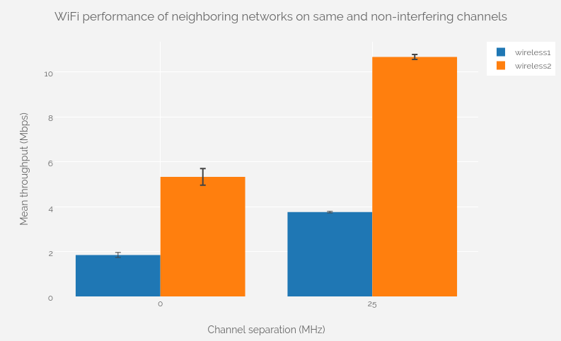
Figure 4: The throughput of the "wireless1" network (blue) increases from about 1.85 Mbps to 3.75 Mbps when a nearby network, "wireless2", moves from the same channel to a non-overlapping channel. The throughput of the "wireless2" network (orange) also increases, from 5.32 Mbps to 10.66 Mbps.
We can see that when neighboring WiFi networks operate on the same channel, their throughput is essentially halved, compared to operation on non-interfering channels.
Notes
Exercise
The tutorial above describes how to measure throughput on two networks when the “wireless1” network operates on Channel 1, and the “wireless2” operates on (1) Channel 1 (same channel), and (2) Channel 6 (non-interfering channel).
Extend this experiment; also collect measurements when the “wireless2” network operates on Channels 2, 3, 4, 5, and 7.
You should submit:
- A table showing mean throughput and standard error of the mean for each network, for each channel separation condition (for example, see below). (It should have 14 rows of data.)
| Network | Channel Separation (MHz) | Mean Throughput (Mbps) | Standard Error (Mbps) |
|---|---|---|---|
| wireless1 | 0 | ... | ... |
| wireless2 | 0 | ... | ... |
| wireless1 | 5 | ... | ... |
| wireless2 | 5 | ... | ... |
| ... | ... | ... | ... |
- A plot of this data, similar to the figure shown in the Results section, but including the additional data for when the second network is on Channels 2, 3, 4, 5, and 7.
- Answer the following questions:
- Is the throughput of an 802.11 network on Channel 1 affected when a nearby network is operating on Channel 2? Explain.
- Is the throughput of an 802.11 network on Channel 1 affected when a nearby network is operating on Channel 6? Explain.
- If you have a network “wireless1” on Channel 1, and a neighboring network “wireless2” on Channel 6, does moving the “wireless2” network from Channel 6 to Channel 7 improve performance? Explain.
Using other testbeds
This experiment should run on any testbed with a similar configuration of six nodes, with Atheros 9xxx cards. For example, you may run it on the "grid" testbed at ORBIT, too (although "grid" is typically in very high demand and difficult to get time on). To run it on "grid", you can use a similar process to the one described here to find six Atheros 9xxx-equipped nodes that are close to one another.
Using sb4 on ORBIT
You may also run this experiment on sb4, even though it doesn't have six Atheros 9xxx nodes, because we can replace some of them with Atheros 5xxx nodes. To run this experiment on sb4 at ORBIT, you will have to modify some of the instructions.
In the Prepare the testbed section:
- Instead of SSHing into outdoor, you will SSH into
sb4.orbit-lab.org
- When you first log in to the "sb4" console, you should reset sb4's programmable attenuation matrix to zero attenuation between all pairs of nodes, and configure the switch so that the WiFi NICs are visible to one another. From the "sb4" console, run
wget -qO- "http://internal2dmz.orbit-lab.org:5054/instr/setAll?att=0"


wget -qO- "http://internal2dmz.orbit-lab.org:5054/instr/selDevice?switch=3&port=1"
wget -qO- "http://internal2dmz.orbit-lab.org:5054/instr/selDevice?switch=4&port=1"
wget -qO- "http://internal2dmz.orbit-lab.org:5054/instr/selDevice?switch=5&port=1"
wget -qO- "http://internal2dmz.orbit-lab.org:5054/instr/selDevice?switch=6&port=1"
wget -qO- "http://internal2dmz.orbit-lab.org:5054/instr/selDevice?switch=7&port=1"
wget -qO- "http://internal2dmz.orbit-lab.org:5054/instr/selDevice?switch=8&port=1"
- Load the disk image onto node1-3, node1-4, node1-5, node1-6, node1-7, node1-8 on sb4:
omf-5.4 load -i wifi-experiment.ndz -t node1-3.sb4.orbit-lab.org,node1-4.sb4.orbit-lab.org,node1-5.sb4.orbit-lab.org,node1-6.sb4.orbit-lab.org,node1-7.sb4.orbit-lab.org,node1-8.sb4.orbit-lab.org
- Turn on those same nodes:
omf tell -a on -t node1-3.sb4.orbit-lab.org,node1-4.sb4.orbit-lab.org,node1-5.sb4.orbit-lab.org,node1-6.sb4.orbit-lab.org,node1-7.sb4.orbit-lab.org,node1-8.sb4.orbit-lab.org
- Designate the six nodes as follows: node1-3 as AP for wireless1, node1-4 as STA 1 for wireless1, node1-5 as STA 2 for wireless1, node1-6 as AP for wireless2, node1-7 as STA 1 for wireless2, node1-8 as STA 2 for wireless2.
In the Configure the wireless access points section:
- Use node1-3 as AP for wireless1
- Use node1-4 as STA 1 for wireless1, and node1-5 as STA 2 for wireless1
- Use node1-6 as AP for wireless2
- Use node1-7 as STA 1 for wireless2, node1-8 as STA 2 for wireless2. These two nodes have Atheros 5xxx wireless cards, rather than the Atheros 9xxx cards. On these nodes (node1-7 and node1-8), you will have to manually load the driver with
modprobe ath5k
before running
ifconfig wlan0 up
(If you see the error message "wlan0: ERROR while getting interface flags: No such device" when bringing up the "wlan0" interface, it's probably because you haven't loaded the driver.)
- You will have assigned different IP addresses to some of your wireless interfaces, so you should modify the IP addresses in the
pingcommands accordingly.
In the Neighboring networks on the same channel and subsequent sections:
- You will have assigned different IP addresses to some of your wireless interfaces, so you should modify the IP addresses in the
iperfcommands accordingly.
Using non-ORBIT testbeds
To use another testbed that isn't at ORBIT, you may need to install some software or do some other configuration steps that are already prepared on the wifi-experiment.ndz disk image on ORBIT.
To create the wifi-experiment.ndz disk image, I started from a baseline Ubuntu 14.04 disk image. Then I installed some software from the Ubuntu package repositories:
apt-get update
apt-get -y install git hostapd iproute2 dnsmasq iptables haveged aircrack-ng
I installed the create_ap tool, which makes it easy to set up a device as a WiFi access point:
git clone https://github.com/oblique/create_ap.git
cd create_ap
make install
I also un-blacklisted the ath9k driver, i.e.
rm /etc/modprobe.d/blacklist-ath9k.conf
so that the ath9k module is loaded at boot. Alternatively, you can manually load the module on each boot with
modprobe ath9k